- Speaker Sound Generator (SSG)
- 1. Product Type
- 1.1 HSB series· Mylar cone
· Manual soldering
· Solder pads, wires, spring or connector mounting
- · Polyfoam tray or EPE foam packing
1.2 HSM series
· With housing
· Mylar cone
· Wave soldering compatible
· Pin type
· Polyfoam or Tube Packing
1.3 HSP series
· Paper cone
· Manual soldering
· Solder tabs, wires or connector mounting
· Carton board or EPE foam packing
- 1.4 HSR series· Mylar cone
· Manual soldering
· Solder tabs, wires or connector mounting
- · EPE foam packing
1.5 HSS series
· High temperature polymer cone
· Reflow soldering
· Surface mount type
- · Tape and reel packing
1.6 SPS series
· Built-in with Piezo driver
· Manual soldering
· Solder pads, wires or connector mounting
- · EPE foam packing
2. Part Numbering System
e.g. HSB1115G-8
– Mylar Cone Bare Speaker, Dimension 11 x 15mm, Series G, 8 ohm
HSB1115G8Mylar Cone Bare SpeakerDiameter/
Dimensions of SSG
Series NumberImpedance3. General Characteristics
· SoniCrest Speaker Sizes Range From 6 mm to 100 mm in Diameter
· Paper or Plastic (mylar / polymer) Cones
· Metal or Plastic Frames
· Shielded Magnet or External Magnet
· Mounting With Pins, Wires/Connectors, SMD or Springs
· Wide Frequency Range, 20 Hz ~ 20 KHz
· Rated Power From 1mW To 15 W
· Rich Sound Reproduction
· Impedance 4 ~ 150 ohms
- 4. Working Principle of SSG
A speaker operates when current from an amplifier flows through the coil. The magnetic field created by the current flowing through the voice coil interacts with the magnetic field of the speaker’s magnet, forcing the coil and its attached cone to move back and forth, producing sound output.
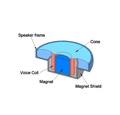
Fig. 1 Internal configuration of a simple SSG (Micro Speaker)
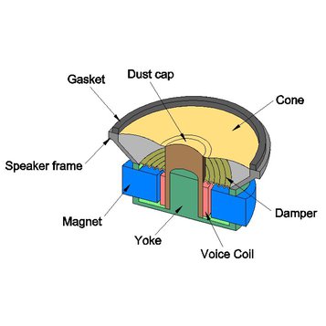
Fig. 2 Internal configuration of a simple SSG (General Speaker)
- 5. Frequency Response
SoniCrest SSG are designed to produce sound according to the frequency of the drive signal applied. The frequency response data given for each SSG is a measure of the effectiveness with which SSG reproduces the different frequencies applied. Frequency response varies from type to type, it is therefore essential to select an appropriate SSG which will meet the specific requirements of the application. All frequency response data given is measured with a sinusoidal wave voltage signal, it should be noted that SoniCrest SSG may not produce the same frequency response as specified if they are driven with any other wave form.
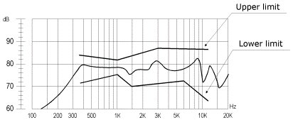
Fig. 3 Typical Response of SSG
- 6. Sound Pressure Level
A speaker’s SPL is rated under 1m1W testing condition in order to compare the SPL of speakers with different rated powers. When a speakers specification shows SPL data at 1m 1W it does not mean that the speaker is actually tested with a 1W signal and the response measured at 1m. A 1W signal may destroy most of the small speakers. Normalization to 1m1W is just for comparison only. The relationship of SPL, measuring distance and input power is
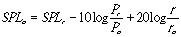
where
SPLo : SPL at 1m1W
SPLr : SPL at measuring distance (r) and with input power (Pr)
Pr : Input power
Po : Reference power (1W)
r : Measuring distance
ro : Reference distance (1m)
SoniCrest speakers are typically tested at 10cm measuring distance with its rated power e.g. 0.4W. Thus, SPL is different to the one stated in the specification sheet due to different testing condition (i.e. measuring distance and input power).
When reporting SPL of speakers, 2 parameters are stated (measuring distance, input power.) The above equation helps converting SPL at 1m1W to SPL with specified measuring distance and input power.
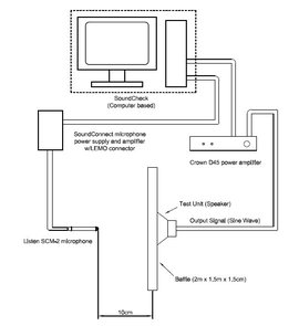
Fig. 4 Test setup for SSG
- 7. Resonance Frequency (f0)
Normally called “f0” or specified as the lowest frequency at which the absolute value of the voice coil electrical impedance peaks. This resonance frequency is determined by the speaker vibration-system mass and suspension compliance such as edge, damper or the like supporting it, and is an important factor in determining the low-pass reproduction limit in the speaker. In addition, f0 may be affected by enclosure design, mounting method and other extenal conditions.
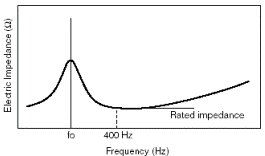
Fig. 5 Composite curve of DC resistance, Coil impedance and reactance
8. Impedance
The impedance of a micro speaker is frequency dependent. The nominal impedance is defined as the minimum value to the right of the f0 (the fundamental resonance) under free field conditions.
- 9. Receiver Sensitivity
The term Sensitivity is used to define the loudness or intensity of a receiver with 1mW at 1kHz applied to the terminals of the receiver which in turn is coupled to a earpiece sealed to an artificial ear according to IEC318.
Sound pressure level is analogues to voltage and therefore output SPL is proportional to applied input voltage.
Comparison with other receivers is only valid if the specifying conditions are the same, i.e. applied input voltage, impedance, earpiece and artificial ear, etc.
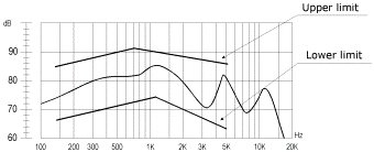
Fig. 6 Typical Response of a Receiver
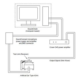
Fig. 7 Test setup of Receiver
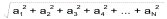
- 10. Total Harmonic Distortion (THD)
Harmonic Distortion is a means for measuring Non-linear Distortion. Non-linear Distortion is a form of progression or processing error that creates signals at frequency that are not necessary present in the input (Unwanted signal).
Total Harmonic Distortion (THD) is the sum of power of all harmonic frequency above the fundamental frequency to the power of the fundamental frequency. It is usually calculated by using the following equation:
THD = Total Distortion/Total Harmonic (usually expressed in %)
Total Harmonic =
Total Distortion =
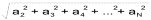
where
a1 : fundamental
a2 : 2nd harmonic
a3 : 3rd harmonic
a4 : 4th harmonic
aN : Nth harmonic
- 11. Simple Application Circuit
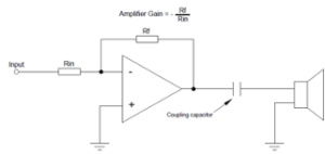 Fig. 8 A very simple application circuit for SSGs
Note: Input level can be adjusted by changing the value of Rf or Rin.
-
- 12. Speaker Installation Guideline
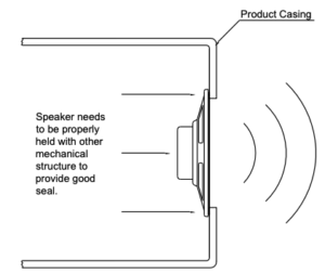
- Fig. 9 General Installation Guideline for SSGs
- 13. Application
· Smart Phones
· iOTs
· Personal Audio
· Headphones
· Laptop Computers
· Smart Speakers
· Automotive Equipment
· Multi-Function Printers
· Wearables
· Kiosk Machine
· High End Toys