- Electro-magnetic Sound Generator (EMSG)
- 1. Product Type
1.1. HC series - · Unsealed structure and non-washable
· With pin, wire or connector
· Manual soldering
· Without oscillation circuit (external drive)*
1.2. HCM series
· Sealed structure and washable
· With sealing label
· Wave soldering compatible
· With pin, wire or connector
· With / without oscillation circuit (self drive / external drive)*
1.3. HCS series
· Surface mount (SMD)
· Re-flow compatible
· Tape and Reel Packaging
· With / without oscillation circuit (self drive / external drive)*
- 2. Part Numbering System
e.g. HCS1212A
– Surface Mount type (SMD), 12mm Diameter Class, Operating Voltage 12V, Series A
|
HCS
|
12
|
12
|
A
|
|
Type of EMSG
|
Diameter/Length
Class of EMSG |
Rated
Operating Voltage |
Series
Number |
*For self drive type EMSG, letter X is indicated at the end of series number, e.g. HCM1212X.
3. General Characteristics
· Rated Frequency – 2 to 3 KHz
· Current Consumption – 10 to 100 mA
· Rated Voltage – 1 to 18 Vo-p
· Miniature Size – 6 to 25 mm in diameter
· Loudness – 75 to 105 dB A (10cm measuring distance)
· Clear Tone
· Mounting – Pins, SMD
· Low cost
- 4. Principle of EMSG
4.1. Without oscillation circuit (external drive)
The diaphragm is magnetically pulled towards the core by the magnet. When input signal (V0-p) is applied, the current flowing through the coil produces a secondary magnetic field, causing the diaphragm to vibrate, hence, producing a sound. The frequency of the sound produced is the same as the frequency of the input signal (V0-p).
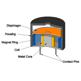
Fig. 1 Internal Configuration of a simple EMSG
- 4.2. With oscillation circuit (self drive)
Traditional self drive type EMSG contain coils which are wound in such a manner to produce L1 for driving, and L2 for feedback purposes. When current flows through coil L1 and the diaphragm begins to vibrate, coil L2 detects its vibration, providing feedback to the base of the transistor so that the oscillation becomes synchronized with the vibration of the diaphragm.
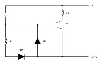
Fig. 2 Traditional schematic diagram of self drive type EMSG
- 5. Frequency Response
SoniCrest external drive EMSGs are designed to produce sound according to the frequency of the drive signal applied. The frequency response data given for each EMSG is a measure of the effectiveness with which EMSG reproduces the different frequencies applied. Frequency response varies from type to type, it is therefore essential to select an appropriate EMSG which will meet the specific requirements of the application. All frequency response data given is measured with a square wave voltage signal, it should be noted that SoniCrest EMSG may not produce the same frequency response as specified if they are driven with any other wave form.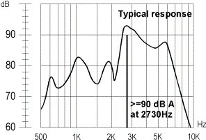
Fig. 3 Typical Frequency Response Example
- 6. Sound Pressure Level
The term Sound Pressure Level (SPL) is used to define the loudness or intensity of sound. There are many external factors that can influence the measurement of SPL. Thus, when reporting SPL, measuring distance is always included. Typical measuring distance of EMSG is 10cm.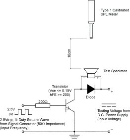
Fig. 4 Recommended Test/Drive circuit for EMSG
- 7. Rated Frequency
The terms Resonance Frequency and Rated Frequency may cause confusion. Resonance frequency is defined as the lowest frequency at which the absolute value of the electrical impedance becomes extremely large. Rated frequency is the recommended application frequency at which optimum SPL can be achieved within specification control. The rated frequency of JL World EMSG is usually from 2kHz to 3kHz. - 8. Rated Input Voltage / Signal
If the voltage signal input is applied to an EMSG component with polarity reversed or alternates from positive peak to negative peak (Vp-p), sound will be generated but it will not always meet the various stated specifications. This is because the reversed polarity input changes the magnetic force direction from “attract” to “repel” or vice versa, which can cause the resonant frequency to deviate from its original point and produce variations in the sound pressure level.
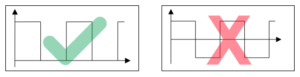 Fig 5 Typical input signal of EMSG (Vo-p)
- 9. Maximum Rated Current Consumption
The rated current consumption designated as Max – mA in the specifications represents the maximum value of the mean current that will flow when the rated voltage and frequency are applied with no limitation to current supply. It is not the maximum allowable current that may be applied to the device, in practice, the peak may be 2 or 3 times the mean current. It is therefore essential to ensure the drive circuit is capable of providing sufficient current, otherwise the sound pressure level may not reach the specified output. - 10. Recommended Drive Circuit
10.1. With oscillation circuit (self drive)
· DC supply.
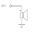
Fig 6 Simple driving circuit for self-type EMSG (VDC)
10.2. Without oscillation circuit (external drive)
· See Fig. 4
(Notes: Application circuit should ideally be capable of current supply that is double the rated current consumption of the sound generator)
- 11. Application
· Point of Sales (POS) system
· Automotive
· Smart Hone Appliances
· Automotive
· Portable Handheld Devices
· Medical Devices
· Computer Motherboards